Found 271 results in 2 milliseconds.

Page

PMT detection unit

Skip breadcrumb navigation Breadcrumb Freiberg Instruments Products Luminescence Dating and Dosimetry lexsygsmart Configuration options PMT detection unit PMT detection unit High-precision detection for groundbreaking analysis results Interested? Get in touch! Contact now Standard UV-VIS PMT unit (300 – 650 nm) Standard UV-VIS PMT unit (280 – 650 nm) standard detection unit for application in luminescence dating and dosimetry bi-alkaline cathode PMT (HAMAMATSU H7360-02) sensitivity range: 300-650 nm peak sensitivity: 420 nm ( 3.1 E5 counts s -1 pW -1 ) dark counts typ. <100 cts photon counter counting linearity (random pulses, 10% loss) 6.0 E6 cps UV-VIS optics Standard UV-VIS PMT unit (280 - 650 nm) Extended UV-VIS PMT unit (160 – 630 nm) for standard applications in luminescence dating and dosimetry detection unit with standard bi-alkaline cathode PMT (Electron Tubes 9235QB) sensitivity 160-630 nm peak sensitivity: 30% quantum efficiency @ 200 nm and 350 nm dark count typ. 300 cts photon counter counting linearity (random pulses, 10% loss) UV-VIS optics Red enhanced UV-VIS PMT unit (300 – 720 nm) Red enhanced UV-VIS PMT unit (300 – 720 nm) necessary/useful if standard UV-VIS PMT sensitivity in the yellow to red wavelength band is insufficient useful e.g. for quartz (flint)/calcite orange-red or feldspar red luminescence measurements thermoelectric/air cooled GaAsP photocathode PMT (HAMAMATSU) sensitivity: 300 – 720 nm peak-sensitivity: 40% quantum efficiency @ 580 nm cooling max. 35 °C below room temperature cooling time approx. 5 min typically 100 cps dark signal at 0°C photon counting system counting linearity (random pulses, 10% count loss) 1.5 E6 cps UV-VIS optics Red enhanced UV-VIS PMT unit (300 - 720 nm) VIS-NIR PMT unit (380 – 890 nm) VIS-NIR PMT unit (380 – 890 nm) required for RF dose determination employing the 865 nm potassium feldspar emission required for 880 nm IRPL detection useful/necessary for any other measurements where red and NIR sensitivity is needed thermoelectric/air cooled GaAs photocathode PMT (HAMAMATSU H7421-50) sensitivity: 380 – 890 nm, peak-sensitivity: 12% quantum efficiency @ 800 nm cooling max. 35 °C below room temperature cooling time approx. 5 min typically 60 cps dark signal at -10°C (125 cps at 0°C) photon counting system counting linearity (random pulses, 10% count loss) 1.5 E6 cps includes UV-NIR optics VIS-NIR PMT unit (380 -890 nm)

Product

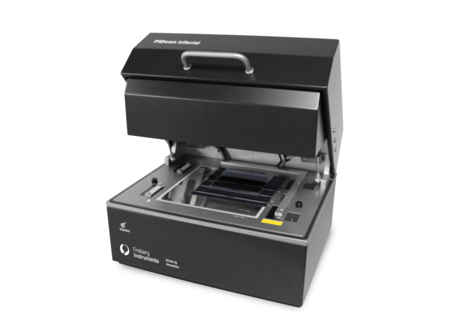
PIDcon bifacial

Skip breadcrumb navigation Breadcrumb Freiberg Instruments Products Potential Induced Degradation PIDcon bifacial PID con bifacial Quality Control Solution for Bifacial PERC/PERC+, HIT, Topcon, c-Si Solar Cells, Mini Modules, and More Interested? Get in touch! Contact now Product Sheet Skip menu Quick navigation Features Applications Specifications Technology Contact Benchtop PID tester for c-Si solar cells and mini-modules PID detection at cell level Research, Production & Quality Control of PERC, AL-BSF, PERC+, bifacial PERC, PERT, PERL and IBC solar cells No climate chamber necessary Features & Benefits Measurements of cells Test duration: 4 hours (typical) Voltage: ± 1.5 kV Module vs. Cell level PID test Applications Production Monitoring Potential Induced Degradation (PID) is a significant reliability issue in photovoltaic (PV) power plants. It is crucial to assess the susceptibility of products to PID early in the production… Learn more EVA Evaluation The PIDcon allows for the investigation of how EVA foil affects PID susceptibility using a sample stack that simulates a module. To perform the test, the user simply places a solar cell, the EVA… Learn more Solar Cell Classification Potential Induced Degradation (PID) poses a significant reliability issue in PV power plants, making it essential to assess products for their susceptibility to PID. The PIDcon system enables… Learn more Mini-module Classification Potential Induced Degradation (PID) is a critical reliability issue in PV power plants, making it essential to assess products for their susceptibility to PID. The PIDcon system helps… Learn more Glass Evaluation For more information please read:[1] V. Naumann, Ursachenanalyse und physikalische Modellbildung für potenzial-induzierte Degradation von Silizium-Solarzellen, Dissertation,… Learn more With our PIDcon bifacial testing device, module manufacturers can perform reliable quick tests of solar cells and encapsulation materials during production. Dr. Christian Hagendorf Key Account Manager Interested? Our experts are happy to assist you. Get in touch! Contact us now! Specifications Type Stress Recovery PID-s front 85 °C, +1.5 kV 85 °C, -1.5 kV PID-p rear 85 °C, +1.5 kV, without illumination 85 °C, dark storage or illumination PID-c rear 85 °C, +1.5 kV, with illumination Not possible Lamination 150 °C, 20 min Sample size up to 210 x 210 mm Suitable for For PERC, AL-BSF, IBC, PERC+, bifacial PERC p- and n-type Measurement of Measurement of: R parallel , leakage current, IV curve under illumination Download Product Sheet PDF (640 KB) Technologies Physical Nature of PID-s In the field a large potential between the front glass surface and the solar cells in a module can occur and a shunting of the p-n junction of a Si solar cell and accordingly a decrease in… Learn more Comparison of PID Test Methods The PIDcon test has the following advantages compared to other methods:Short duration (usually 4–8h), High variability: test of solar cell, mini-module, glass and EVA, Good control of test… Learn more Dependencies of PID Susceptibility For more information please read:[1] V. Naumann, Ursachenanalyse und physikalische Modellbildung für potenzial-induzierte Degradation von Silizium-Solarzellen, Dissertation,… Learn more Conductance Test and Power Loss Furthermore an easy pass or fail criterion after finishing the PID measurement is suggested. It is assumed that an efficiency loss of 3% at the end of the PID test lead to a fail of the solar… Learn more Get in touch Do not hesitate to contact us – we are available to assist you with any inquiries or requests. Use our inquiry tool or reach out via email: sales @ freiberginstruments.com
Technology

PIDStudio

PIDStudio User friendly and advanced operating software PIDStudio is a cutting-edge, user-friendly software that is continuously updated and improved based on user feedback. It allows for easy handling and provides intuitive functionality. With PIDStudio , you can output and compare key parameters from multiple measurements, including: Parallel Resistance Conductance Power Loss Leakage Current Temperature Humidity High Voltage Key Features: User-friendly interface Export functionality Customizable recipes Pass/fail criteria Comprehensive analysis tools Control of multiple devices This software is designed to simplify and enhance the PID testing process. Get in touch Do not hesitate to contact us – we are available to assist you with any inquiries or requests. Use our inquiry tool or reach out via email: sales @ freiberginstruments.com

Page

Our people

Our people We are Automation and Metrology Experts Meet the Experts Behind Our Innovations At Freiberg Instruments, our team is the foundation of our success. United by a commitment to precision, innovation, and customer satisfaction, we deliver cutting-edge solutions for semiconductors, photovoltaics, materials science and more. Our engineers, scientists, and professionals combine diverse expertise with a passion for progress, tackling challenges and shaping the future of automation and metrology. Discover the people who drive our success and make Freiberg Instruments a trusted partner worldwide. Dr. Kay Dornich Chief Executive Officer +49 3731 419 540 Send E-Mail LinkedIn profile Diana Trinks Executive Assistant Get to know +49 3731 419 54 24 Send E-Mail Sales Ing. Thanga Kumar Sales Director Get to know +49 3731 419 540 Send E-Mail LinkedIn profile Dr. Ing. Hans-Arthur Bradaczek Head of X-ray Technology +49 3063 224 079 +49 176 576 623 68 Send E-Mail Burkhard Winkler Senior Sales Manager SEMI & Automation Get to know +49 3731 419 54 52 Send E-Mail Dr. Christian Hagendorf Key Account Manager Get to know +49 3731 419 54 35 +49 176 880 964 48 Send E-Mail LinkedIn profile After-sales-service & Support Martin Ferkinghoff Head of Service Get to know +49 176 459 072 19 Send E-Mail LinkedIn profile Marcus Richter Application & Service Engineer Get to know +49 3731 419 540 Send E-Mail Research & Development Dr. Nadine Schüler Head of Research & Development Get to know +49 3731 419 540 Send E-Mail LinkedIn profile Dipl.-Ing. (DH) Marcus Göhler Head of Electronics Development Get to know +49 3731 419 540 Send E-Mail LinkedIn profile Dipl.-Ing. Oliver Simmank Head of Software Development +49 3731 419 540 Send E-Mail Application & Product Management Dipl.-Ing. Andreas Richter Quality Management Officer +49 3731 419 54 21 Send E-Mail LinkedIn profile Dr. Viktoriia Nikonova Product Manager SPV/SPS Get to know +49 3731 419 54 66 Send E-Mail LinkedIn profile Marco Meyer Product Manager OSL +49 3731 419 54 36 Send E-Mail Sebastian Lesch Application XRD +49 3731 419 54 71 Send E-Mail Pauline Taubert Application ESR +49 3731 419 540 Send E-Mail Rico Schweigel Application ESR +49 3731 419 54 44 Send E-Mail Human Resources Nancy Gallasch Human Resources Manager +49 3731 419 54 93 Send E-Mail One team, over 100 individuals, all Driven by Innovation Discover more Quality and Certification Learn more News Learn more

Page

Optional accessories

Optional accessories for lexsyg research Sample cups/discs Learn more Aliquot preparation kit Learn more LED head lamp Learn more Vacuum pump Compact rotary vane pump, Automatically controlled by the lexsyg device , Low weight, Low maintenance, Includes all necessary seals, flanges and pipes, Learn more Air compressor Learn more

Page

Optional accessories

Optional accessories for lexsyg smart Additional sample carousel Each lexsyg smart TL/OSL reader is delivered with two exchangeable sample carousels with 50 samples positions (automatic changer) for ∅=10 + 0,0/-0,2 mm (max. thickness 1 mm sample discs). … Learn more Sample cups/discs Sample cups/discs are designed to provide excellent thermal conductivity. They are cleaned and vacuum sealed (20 pcs per/package) separately. Stainless steel, VA 1.4301, most popular, for… Learn more Aliquot preparation kit Our brand new Aliquot preparation kit includes a stamp and a template for quick silicon stamping on hundreds of sample cups or discs. Learn more LED head lamp 660 nm ± 15 nm, Two intensities, No side bands, Learn more Air compressor Maximum pressure: 8 bars, Low noise (33 dB), Weight (22 kg), Learn more Get in touch Do not hesitate to contact us – we are available to assist you with any inquiries or requests. Use our inquiry tool or reach out via email: sales @ freiberginstruments.com

Application

Optically stimulated Luminescence dating of quartz (OSL)

Optically stimulated Luminescence dating of quartz Exposure to light reduces the Optically stimulated Luminescence (OSL) signal from quartz and provides the basis for dating the event of light exposure and thus the sedimentation. Age range Few years (depending on signal intensity and sensitivity of equipment for which the lexsyg systems are especially developed) Up to ~150-200,000 years (depending on dosimetry) Sediment types Aeolian sediments like dunes or loess are suited very well Lacustrine and fluvial deposits can be dated Glaciogenic sediments are difficult Used for Geomorphological reconstruction Palaeoenvironmental reconstruction Earth quake history River system reconstruction Chronostratigraphy Stimulation wavelengths for quartz Blue Green UV Murray AS & Wintle AG (2000) Luminescence dating of quartz using an improved single-aliquot regenerative-dose protocol. Radiation Measurements 32, 57-73. Principle of the single aliquot regeneration (SAR after Murray & Wintle, 2000) method to determine the palaeodose, where the natural luminescence signal is interpolated on the regenerated signal obtained by irradiation of the same aliquot Related Solutions and Industries: Luminescence Dating and Dosimetry Matching Products TL/OSL series lexsygsmart The most sensitive TL/OSL reader Learn more TL/OSL series lexsygresearch The most advanced TL/OSL reader Learn more Get in touch Do not hesitate to contact us – we are available to assist you with any inquiries or requests. Use our inquiry tool or reach out via email: sales @ freiberginstruments.com

Product

Omega/Theta XRD

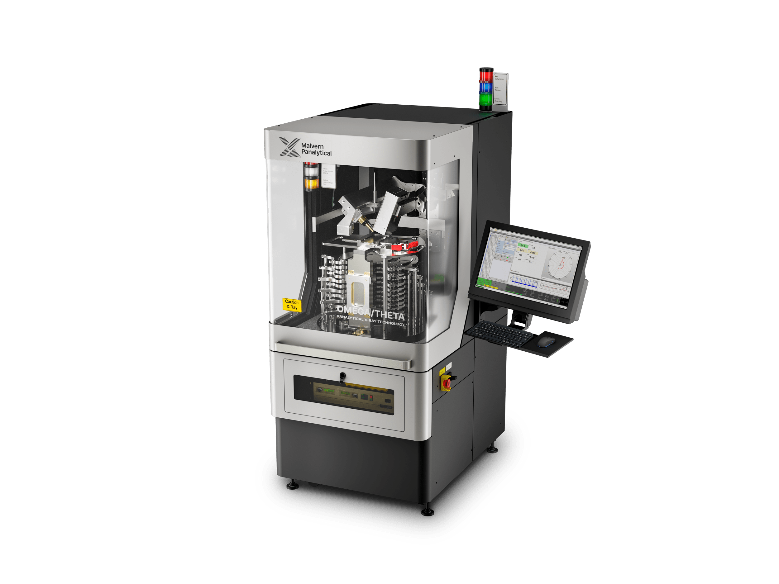
Skip breadcrumb navigation Breadcrumb Freiberg Instruments Products X-ray Diffraction Omega/Theta XRD Omega/Theta XRD for ultra-fast crystal orientation, crystal alignment in production, quality control, rocking curve measurements, material research and more Exclusively through Malvern Panalytical Contact for demo Product Sheet Skip menu Quick navigation Features Applications Technology Options Software Contact Established Omega-scan method All measurements are automated and can be accessed from the user-friendly software interface Using the Omega Scan, the complete lattice orientation can be determined in on crystal rotation (5 seconds) The Theta Scan is more flexible, but results only in one orientation component per scan Materials Our Omega/Theta XRD systems enable precise analysis across a wide range of materials. Designed for flexibility and exceptional performance, they effortlessly meet the most demanding industry requirements. Si SiC AIN GaAs Quartz LiNbO₃ BBO and more Features & Benefits < 5 s/sample Measurement speed Up to 450 mm Sample size 0.1 arc sec Angular resolution of the diffractometer Ultra-fast crystal orientation measurement Ultra-fast crystal orientation measurement Single crystal diffractometer Fully automated complete lattice orientation measurement of single crystals Ultra-fast crystal orientation measurement using Omega-scan method Automated rocking-curve measurement Angular resolution of the diffractometer: 0.1 arc sec. Sample size up to 450 mm Appropriate for production quality control and research User friendly and cost effective Convenient sample handling and easy to operate Advanced, user-friendly software Low energy consumption and operating costs Modular design and flexibility Various upgrade options Customization to the users' requirements Omega-scan diagram (SiC) Turbine blade, map of one orientation component (Si, Ge) wafer, orientation map lattice parameter map Established Omega-scan method The Omega/Theta X-ray diffractometer is a fully automated vertical three axes diffractometer for orientation determination for various crystals using Omega-Scan and Theta-Scan methods and rocking curve measurements. The large and spacious design can accomodate samples and sample holders up to 450 mm in length and up to 30 kg weight. All measurements are automated and can be accessed from the user-friendly software interface. Using the Omega Scan, the complete lattice orientation can be determined in on crystal rotation (5 seconds). The Theta Scan is more flexible, but results only in one orientation component per scan. The tilt angle can be determined with very high precision; up to 0.001° using the Theta Scan. For all other crystal directions the precision depends on the angular difference to the surface perpendicular. The system is modular and has been equipped with many different extensions for special purposes like shape or flat determination, mapping and diverse sample holders. The sample tilt is detected by an optical measurement, and can be used to correct the resulting orientation. Highest precision Measurement speed: < 5 secs/sample Easy integration into process line MES and/or SECS/GEM interfaces Typical standard deviation tilt (example: Si 100): < 0.003 °, minimum < 0.001 ° Applications Crystal Surface Orientation Mapping Even within a single crystal, slight variations in crystal orientation can occur across the surface, often due to internal strains from lattice defects. Similarly, well-grown thin films can… Learn more 3D Mapping of Crystalline Turbine Blades The high-temperature creep resistance of turbine blades made from single-crystal NI-superalloys is influenced by the deviation from the target orientation. A customized XRD system, with its 3D… Learn more Samples with a wide variety of geometry & size The industrial synthesis of single crystals begins with large, heavy boules and is processed down to smaller forms, such as wafers or blanks. In experimental growth, tiny cylinders are produced.… Learn more Marking and measuring of in-plane directions The Omega Scan provides a complete crystal orientation in a single measurement, allowing for the direct identification of in-plane directions. This feature is particularly useful for marking… Learn more Crystal quality Crystal quality cannot be directly measured, but several physical properties can be assessed and compared to standards for pure, homogeneous crystals. One such property is the half-width of an… Learn more NLO Materials: Crystal Quality & Optical Axis Orientation Unlike typical inorganic metals, semiconductors, and insulators, NLO materials feature more complex crystal structures with lower symmetry. This structure creates a highly anisotropic environment… Learn more Omega/Theta XRD – Exclusively through Malvern Panalytical This product is distributed by our trusted partner. Contact for demo Technologies Omega-scan Ultra-Fast Orientation Measurement for Single Crystals Learn more Theta-scan Precision X-ray Method for Single Crystal Orientation Learn more Accessories & Options Automatic X-Y mapping stage The mapping stage allows to explore the whole sample surface using a controlled grid pattern. An Omega/Theta XRD can easily accommodate the additional xy-positioning stage on top of the… Learn more Omega/Theta - Stacking stage These need to be aligned prior to sawing process. Freiberg Instruments provides a convenient holder system to align ingots using Omega-scan. The entire stack is transferred to wire saw. Parallel… Learn more Omega/Theta - Rocking curve measurement The Rocking Curve of a crystal reflection indicates the quality of the crystalline lattice. This can be down pointwise for fast checking or in combination with a mapping tool to receive a quality… Learn more Omega/Theta - Customized sample holders for large samples up to 590 mm diameter, max. sample mass = 30 kg, additional fixtures for complex sample geometry on request, Learn more More Options Laser scanner for sample shape measurement Photographic camera and image processing for flat and notch detection Additional sample rotation axis for 3D mapping Secondary channel-cut collimator (analyzer) Equipment for sample adjustment Software XRDStudio Multiple Operating ModesOperator Mode: Designed for fixed measurement parameters, ensuring a safe and streamlined workflow. Administrator Mode: Allows for the creation and modification of… Learn more Omega/Theta XRD – Exclusively through Malvern Panalytical This product is distributed by our trusted partner. Contact for demo

Page

Omega/Theta - Stacking stage

Skip breadcrumb navigation Breadcrumb Freiberg Instruments Products X-ray Diffraction Omega/Theta XRD Omega/Theta - Stacking stage Omega/Theta – Stacking stage Industrial production of crystals such as SiC yields thick ingots Interested? Get in touch! Contact now These need to be aligned prior to sawing process. Freiberg Instruments provides a convenient holder system to align ingots using Omega-scan . The entire stack is transferred to wire saw. Parallel sawing saves time significantly. SiC Y3Al5012 Sampler diameter 75 to 200 mm 50 to 65 mm Sample height 6 to 50 mmm 6 to 50 mm number of stacks 12 12

Page

Omega/Theta - Rocking curve measurement

Skip breadcrumb navigation Breadcrumb Freiberg Instruments Products X-ray Diffraction Omega/Theta XRD Omega/Theta - Rocking curve measurement Omega/Theta - Rocking curve measurement Unique insights into lattice quality Interested? Get in touch! Contact now The Rocking Curve of a crystal reflection indicates the quality of the crystalline lattice. This can be down pointwise for fast checking or in combination with a mapping tool to receive a quality map. Measuring a Rocking Curve means measuring in Theta-scan mode, which requires a goniometer. A double crystal is brought into the primary beam path to decrease the spectral width and divergency. However, the side effect is a strongly reduced intensity. Therefore, the double crystal is mounted on a retractable holder to be able to switch it "on" or "off". Rocking curves of a 6H SiC crystal measured along a line on spots of 8 mm distance